

Earthing & Grounding
Cable-to-rod and bar-to-rod joints create permanent paths to grounding electrodes.
Engineered connection geometries
Amiable Impex manufactures AURAWELD® exothermic welding powder, precision graphite moulds and field accessories for reliable grounding and bonding connections.
Common exothermic weld joints are organised by the conductors being connected. Cable-to-cable, cable-to-ground-rod, cable-to-bar, cable-to-surface, bar-to-bar and bar-to-ground-rod moulds support straight, tee and cross geometries across electrical, structural and infrastructure projects.
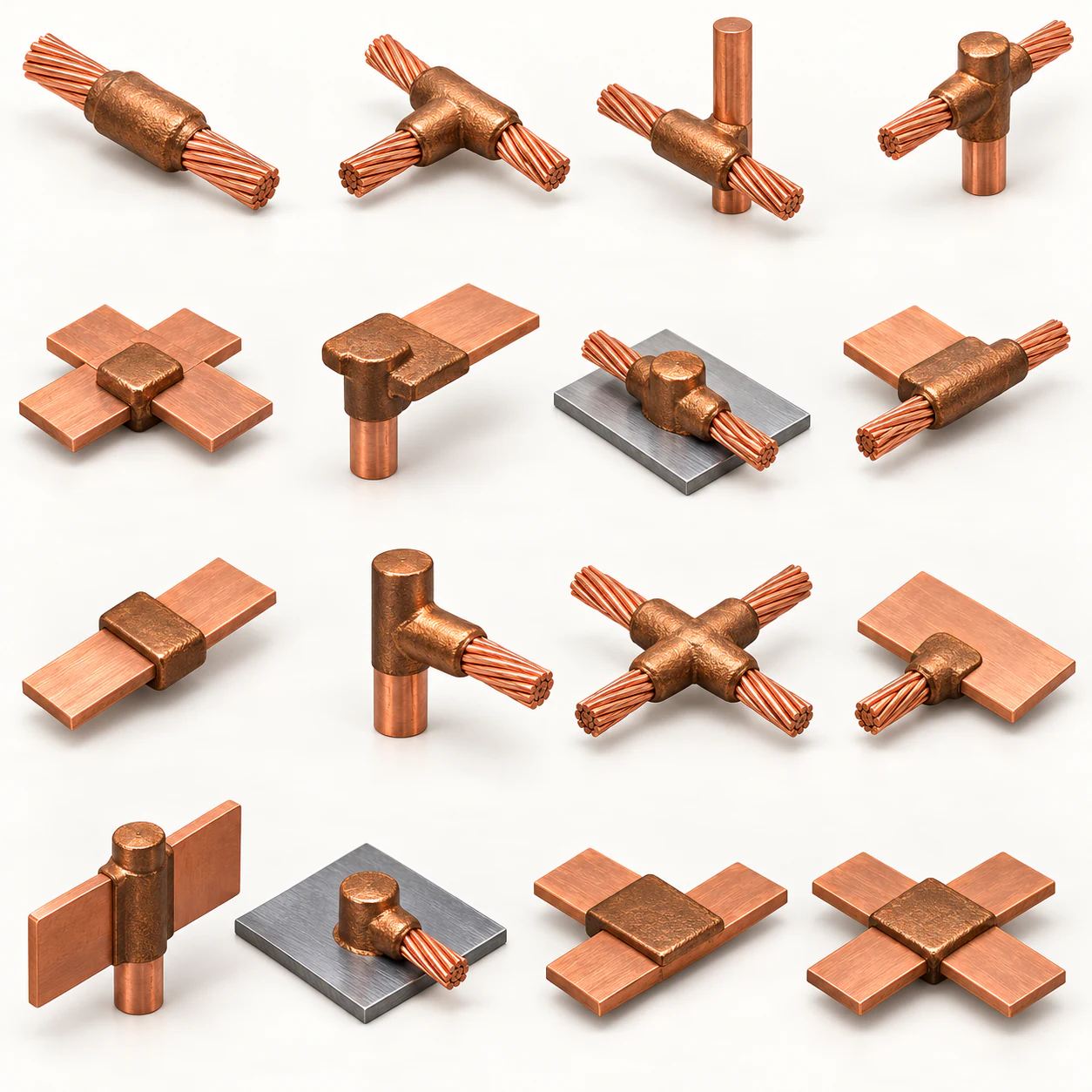
Common graphite mould configurations
Choose a conductor family to compare its standard joint geometries and mould references.
CC Series
Permanent copper conductor connections for straight runs, branches and crossing conductors.
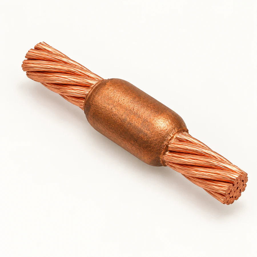 CC-1
Cable To Cable
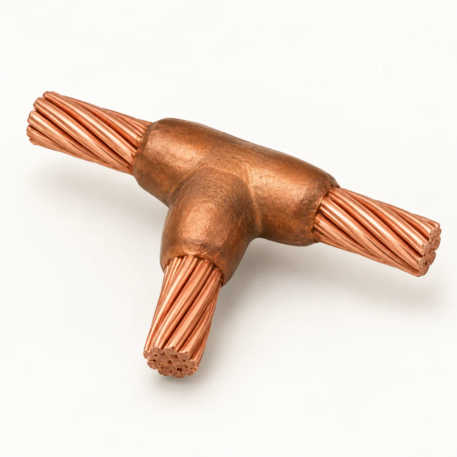 CC-2
Cable To Cable
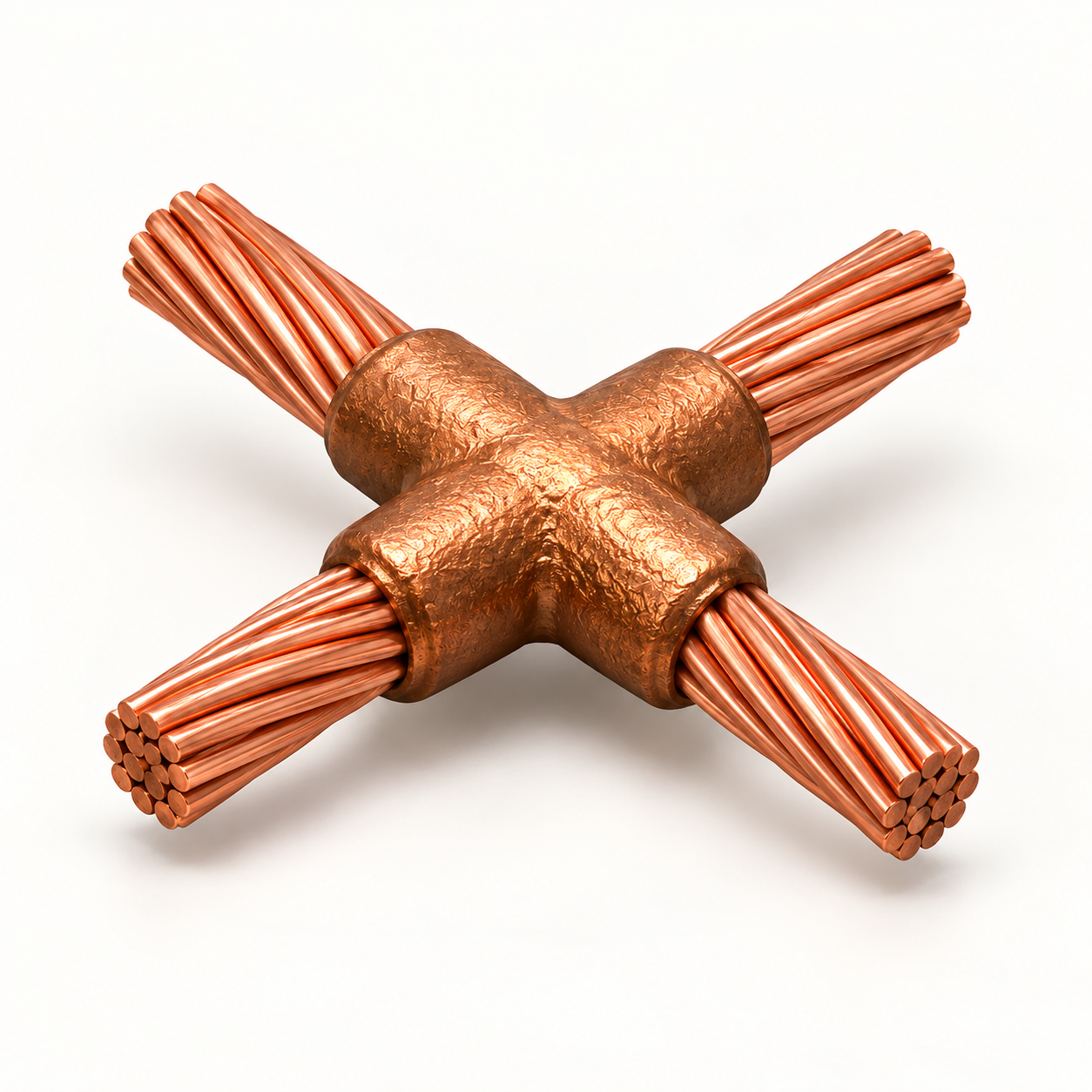 CC-4
Cable To Cable
CR Series
Cable-to-earth-electrode joints for grounding grids, lightning protection and earthing systems.
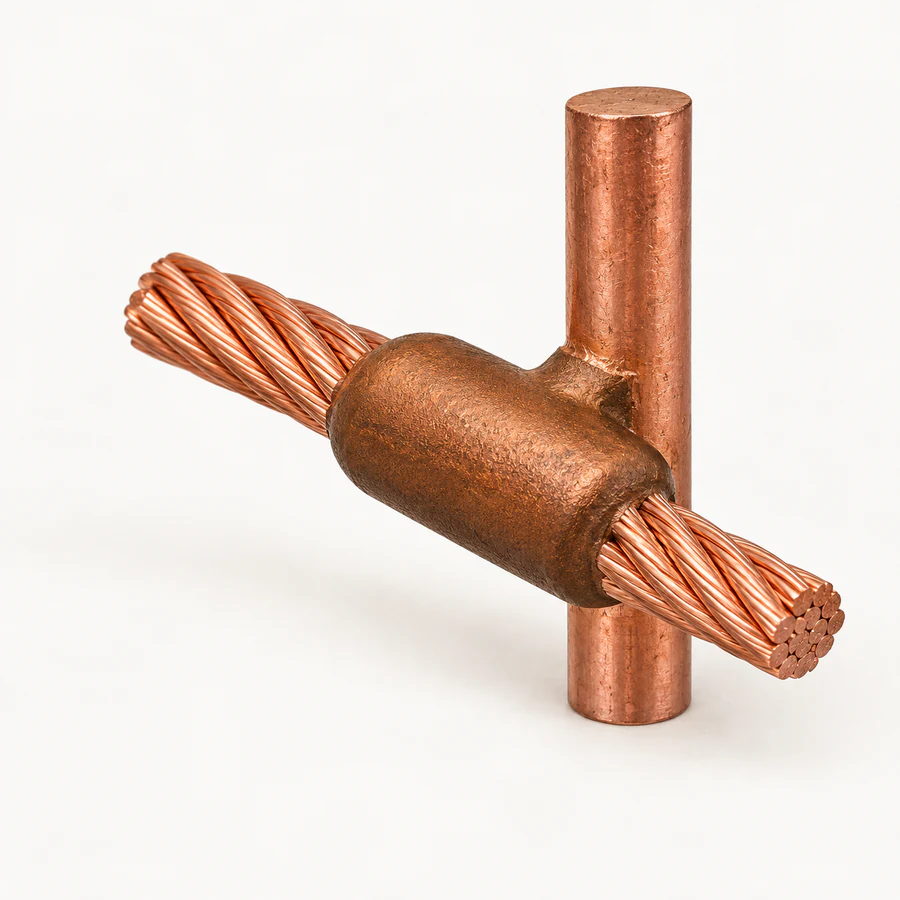 CR-1
Cable To Ground Rod
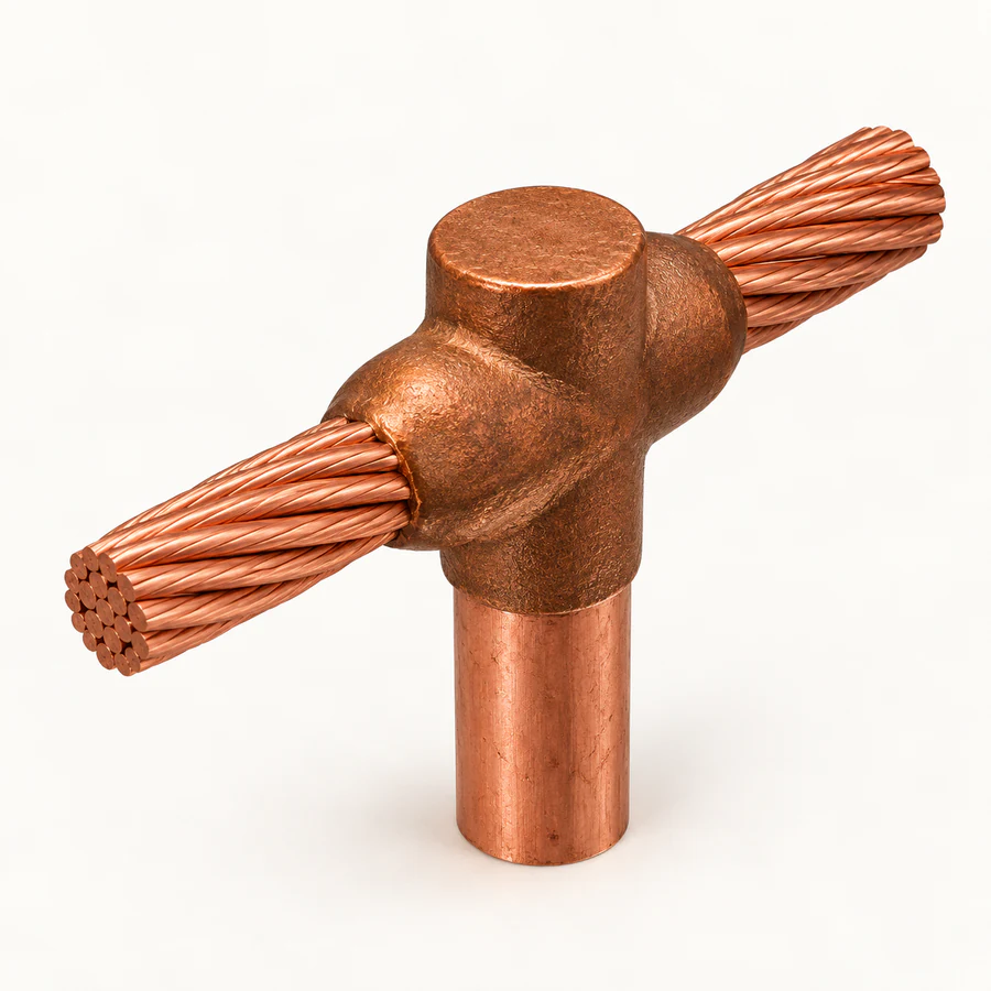 CR-2
Cable To Ground Rod
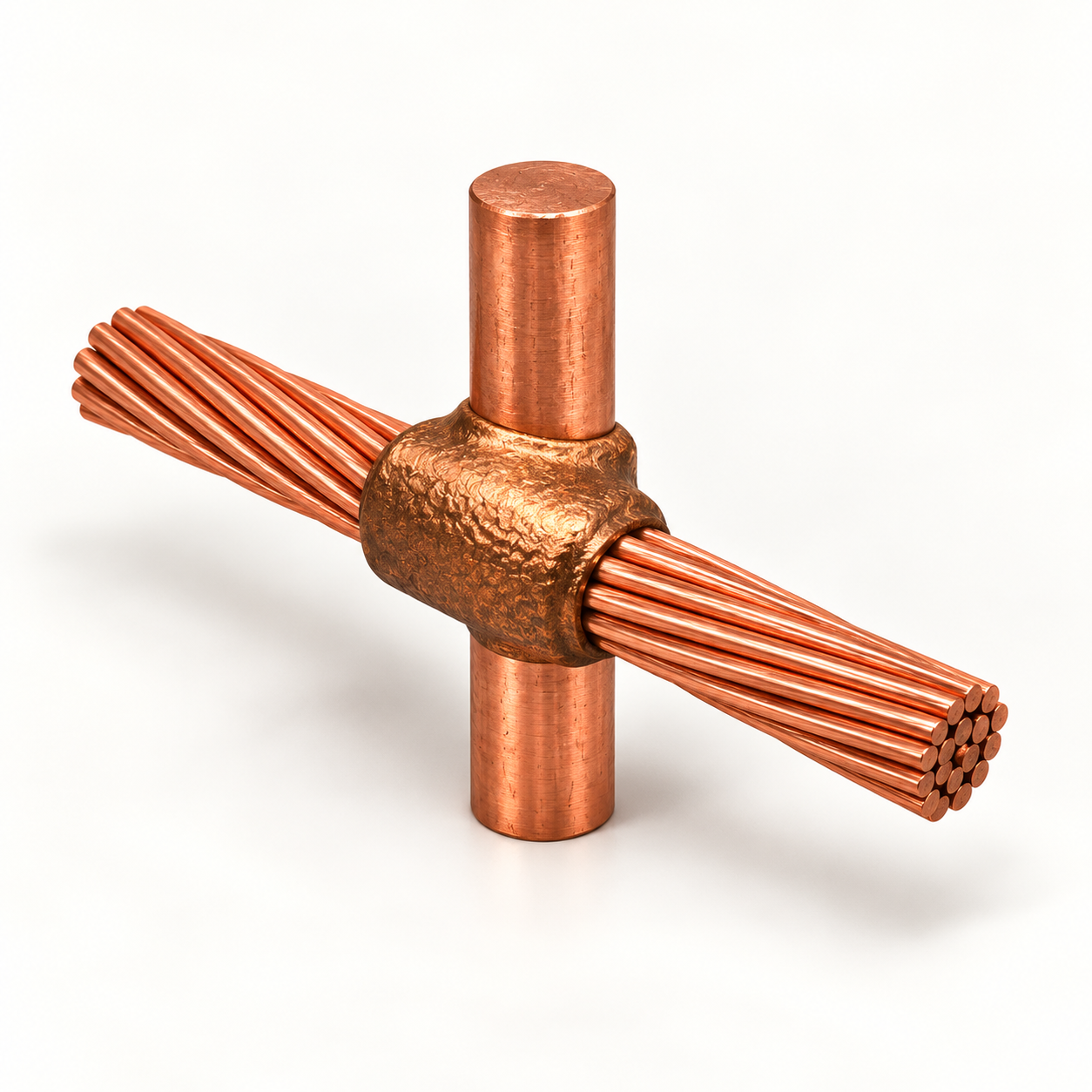 CR-3
Cable To Ground Rod
CB Series
Cable-to-copper-bar connections for busbars, earthing bars and power-distribution assemblies.
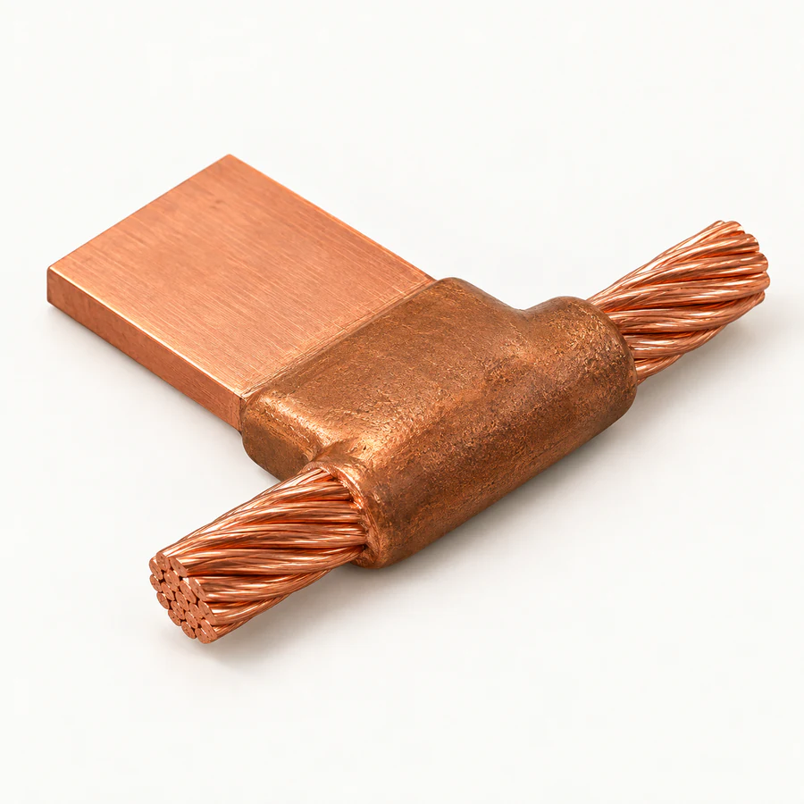 CB-4
Cable To Bar
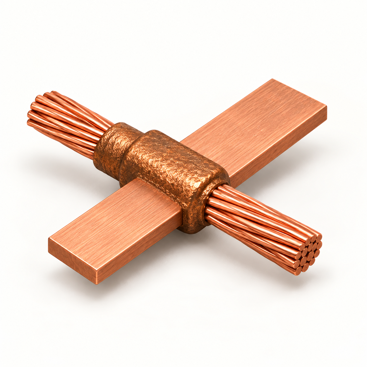 CB-4
Cable To Bar
CS Series
Cable bonds to steel or copper surfaces for structures, equipment and grounding networks.
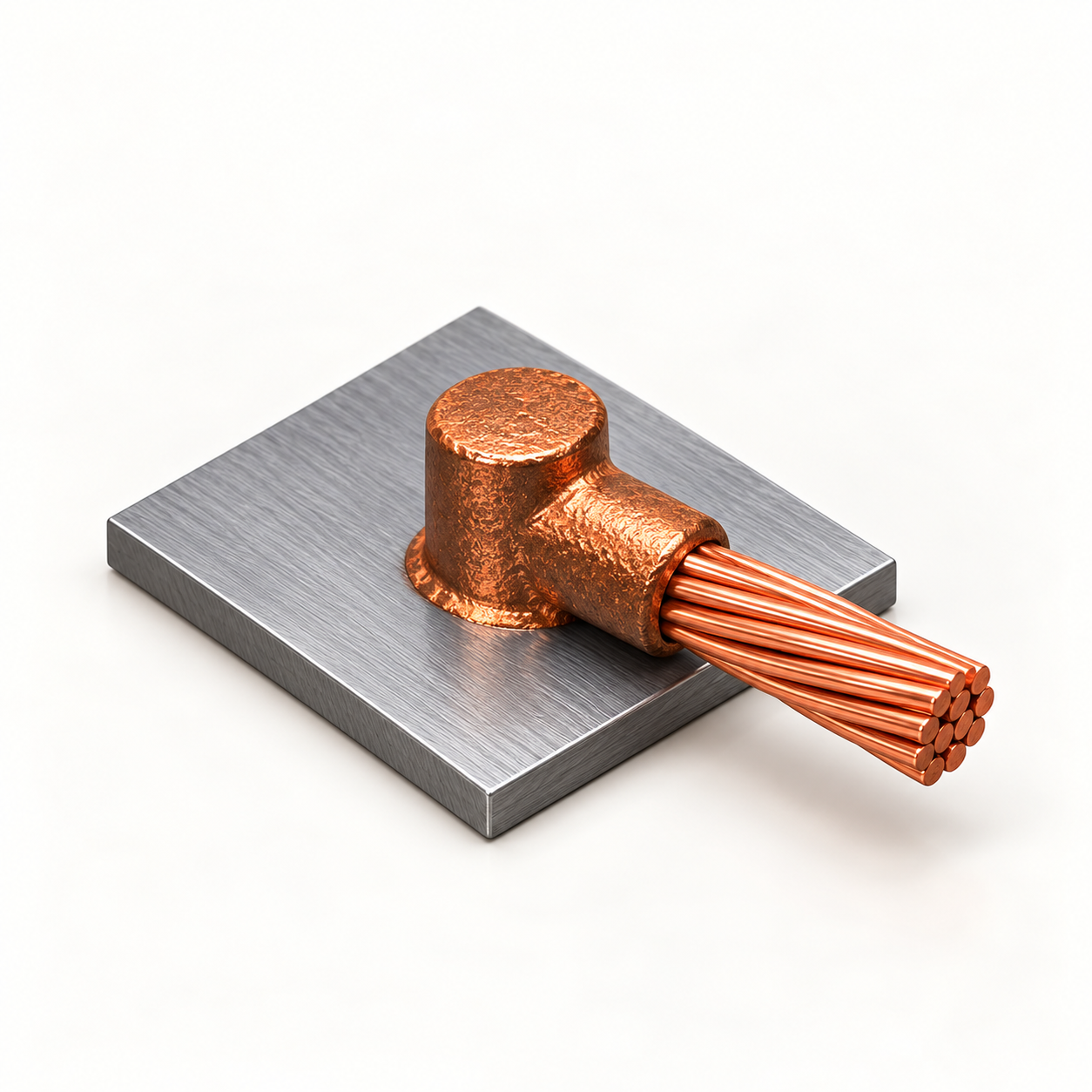 CS-1
Cable To Surface
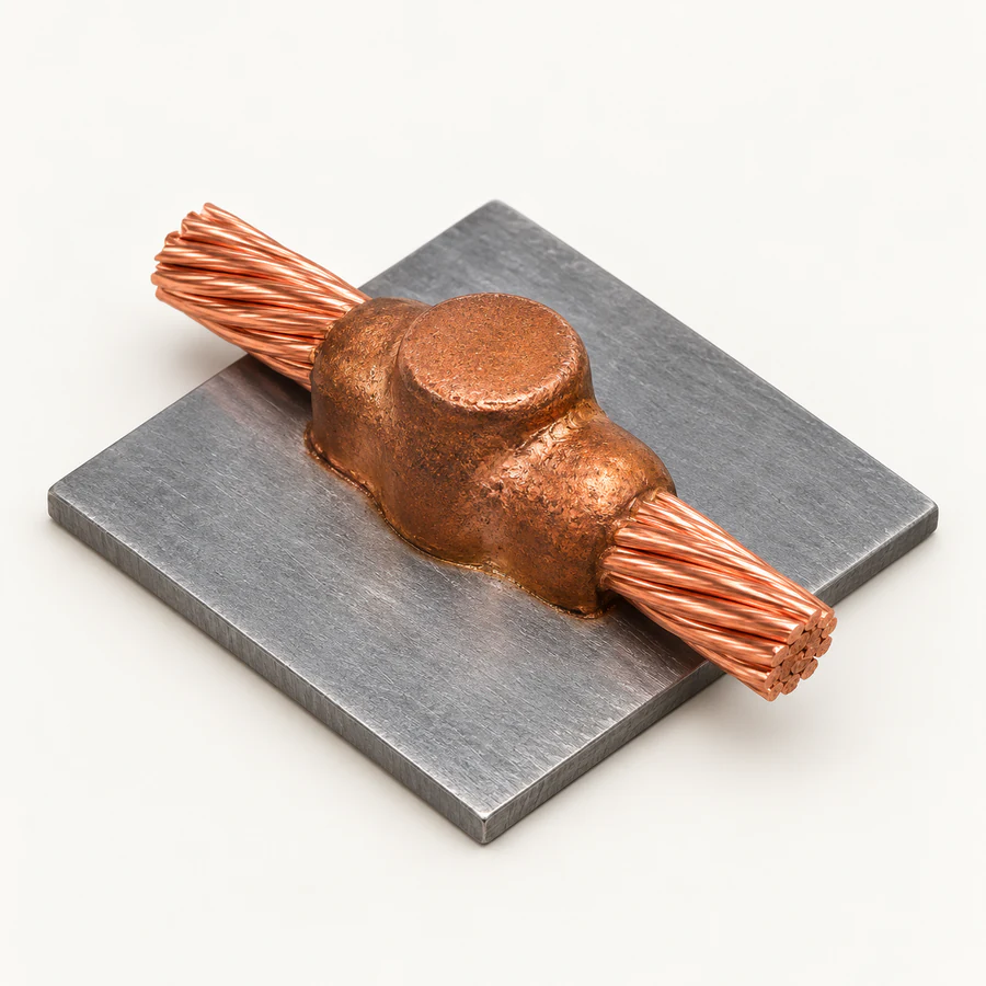 CS-2
Cable To Surface
BB Series
Copper-bar connections for straight, tee, full-cross and half-cross conductor layouts.
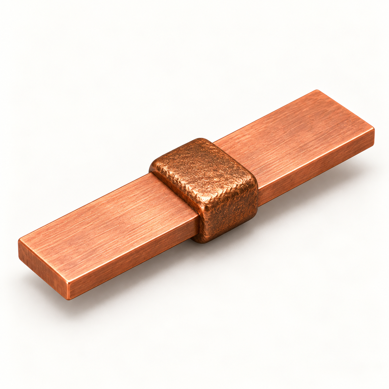 BB-1
Bar To Bar
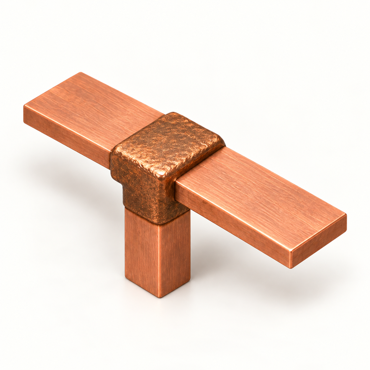 BB-2
Bar To Bar
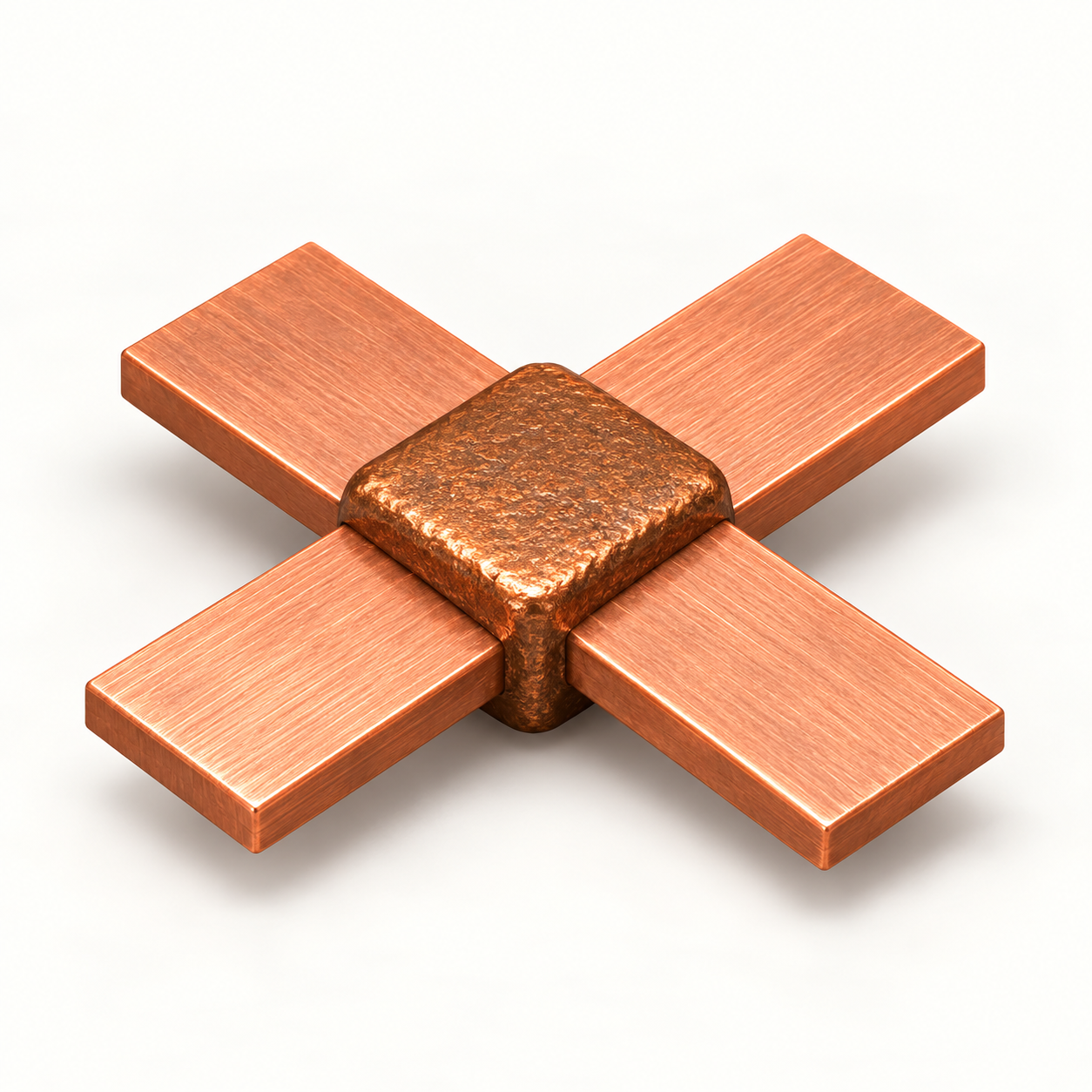 BB-40
Bar To Bar
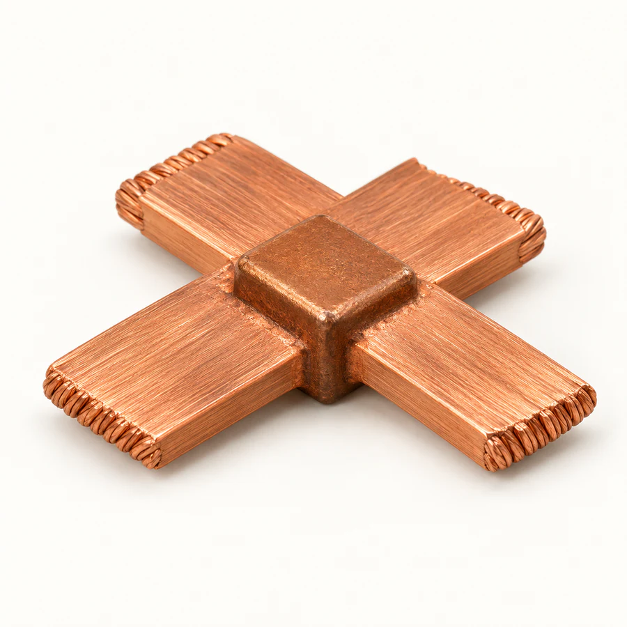 BB-41
Bar To Bar
BR Series
Copper-bar-to-ground-rod joints for grounding electrodes and earthing networks.
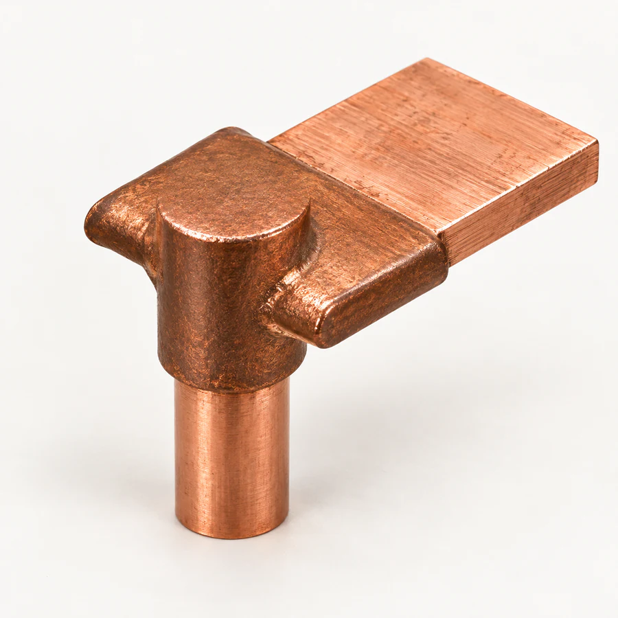 BR-1
Bar To Ground Rod
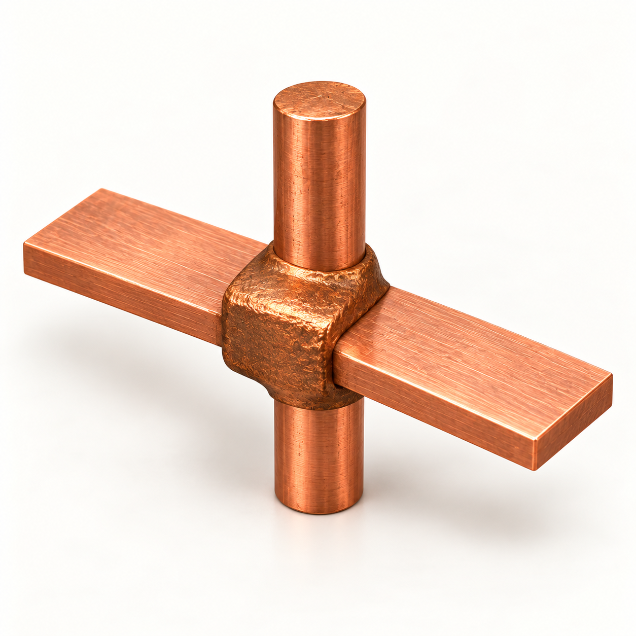 BR-2
Bar To Ground Rod
Where common joints are used
The correct joint geometry helps maintain dependable electrical continuity across grounding, power, rail, telecommunications and structural-bonding systems.
Cable-to-rod and bar-to-rod joints create permanent paths to grounding electrodes.
Cable-to-bar and bar-to-bar joints support reliable current transfer in electrical assemblies.
Cable-to-surface joints bond grounding conductors to steel or copper structures.
Specified cable connections support electrical continuity in railway infrastructure.
Grounding and bonding joints protect towers and communication equipment.
Permanent welded connections support selected pipeline and cathodic-protection systems.
Specify the mould correctly
For an accurate mould and weld-charge recommendation, share the connection details before ordering.
Request a recommendationIdentify whether each component is cable, bar, rod, steel or copper surface.
Provide cable area or diameter, bar size and rod diameter.
Confirm whether the layout is straight, tee, full cross or half cross.
Share the number of connections and installation location for supply planning.
Common joint selection answers
Exothermic weld common joints are standard conductor configurations formed inside a purpose-designed graphite mould. They include cable-to-cable, cable-to-ground-rod, cable-to-bar, cable-to-surface, bar-to-bar and bar-to-ground-rod connections.
Selection begins with the conductor materials, conductor dimensions, required joint geometry and installation orientation. These details determine the mould family, mould code and matching weld-metal charge.
No. The mould cavity is engineered for a defined conductor combination and joint geometry. The specified mould and weld charge should be used for each connection.
Share both conductor materials, their sizes, the required straight, tee or cross arrangement, project quantity and installation conditions. This allows the mould and weld-metal system to be matched correctly.
Need a non-standard connection?
Send the conductor types, dimensions, joint orientation and expected quantity for an application-specific recommendation.